Vehicle
Brake Information
Written By Michael Romano, Mechanical Engineer
Contents:
Page���������������������������������������
Description
2��������������������������������������������� Pedal
Feel
4��������������������������������������������� Brake
Performance
5��������������������������������������������� Brake
Fade
6��������������������������������������������� Brake
Feel and its Benefits
7��������������������������������������������� Master
cylinder and caliper sizing effect on pedal feel
8��������������������������������������������� Stainless
Steel Braided Brake Lines
8��������������������������������������������� Stopping
Force Calculations
9��������������������������������������������� Lug
Nut Torque Effect on Brakes
9��������������������������������������������� Brake
Air Ducts
10������������������������������������������� Rear
Brake Upgrades
11������������������������������������������� Brake
Fluids (information
copied from multiple sources)���
14������������������������������������������� Brake
Bleeding/Flushing
15������������������������������� ����������� 2-Piece rotors
16�������������������������������������������
Warped Rotors and The Truth
17�������������������������������������������
Cross-drilled and Slotted Rotors
18������������������������������������������� Brake
Caliper, fixed, sliding and multi-pistons
19������������������������������������������� Dynamic
Brake Control (Panic Brake Assist)
19�������������������������������������������
Anti-lock Brake
Systems (ABS) (from:
http://www.geocities.com/nosro/abs_faq/
20 ������������������������������������������
Glossary (from
http://www.stoptech.com/)
34������������������������������������������� "Mini
brake test" For Fun
35�������������������������������������������
Appendix with
diagrams, charts and graphs
Little background
on me: I was a brake engineer working at Continental-Teves (trademark: Ate
Brakes) and Ford. The info below is meant to give you a better understanding
of brakes and many things in it are just for information purpose.
3 of the best brake info sites I've
ever found (don't agree with everything, but some things are subjective so
you can decide what you want)
http://www.stoptech.com/technical/
http://www.geocities.com/nosro/abs_faq/
http://www.dba.com.au/technical.asp
Pedal
Feel
First some quick
definitions: Brake Pedal ratio is the measurement of how much mechanical assistance
you are getting from the pedal. Example: a ratio of 4.1 will give you 41 pounds
at the booster input rod for a 10 pound load at the pedal itself.
Dead or lost travel
is how much pedal stoke is required before you actually start stopping.
Dead Travel or
Lost travel and overall poor pedal feel is made up of the following:
[(Travel as measured
at the brake service pedal assembly pin (where the booster connects)]
(Imagine traveling
from the pedal through the brake system to the rotor, all lost travel must
be multiplied by whatever your brake pedal ratio is.)
1. Tolerance between
brake pedal pin and booster input rod. This can be quite a bit for systems
that use a pin mounted brake light switch. If you do have such a switch do
not remove it or take up the slack as your brake lights will be on all the
time. If you don't have a pin-mounted switch just get a tighter bushing. If
you do, you're out of luck.
* will be felt
during first few mm of travel
2. Slack in the
brake pedal assembly itself. To see how good or bad yours is, with the car
off pump the brakes until hard (2-3 pumps) and then grab the pedal with your
hands and see how much it moves around.
* will be felt
through first few mm of travel (I hope)
3. Dash flex. This
can range dramatically from vehicle model to vehicle model. Not much you can
do about this.
*felt during medium
and high decelerations stops on most cars, on Fords dashes flex with the breeze
4. Lost travel
in booster. This is designed to be there to allow for booster expansion due
to climate and use over time. Only adds half an mm (multiplied by the pedal
ratio).
*felt only in the
first few mm of travel
5. Flex of booster
shell. Can be a real problem on some designs. All you can do is try and brace
the booster or replace with a better product.
*felt on medium
and high deceleration stops
6. Design tolerances
in the Master Cylinder. Varies greatly from one to another. Simply, if you
want less lost travel in the TMC (tandem master cylinder), you have to pay
for a more expensive one. A minimum lost travel of about 1-1.5mm is required
for proper and safe operation. However, I've seen some with double that. (Again
multiplied by the pedal ratio)
*felt during first
10mm or so of pedal travel
7. The brake tubes
and ABS unit. Maybe .0000001mm here. Don't worry about it.
8. Brake hoses.
Get steel braided ones, there worth it. Rubber hoses flex quite a bit� under pressure.
*felt almost all
the time
9. Brake Caliper
Piston Roll Back. This is usually the worst offender. Only way to get rid
of this is to get better calipers. Roll back is how far the piston moves away
from the rotor when pressure is released. The bigger the gap, the more you
have to push on the pedal to get contact.
10. Caliper Deflection.
The caliper actually flexing under pressure, like 9 you can only improve this
with better calipers.
*felt during medium
and high deceleration stops
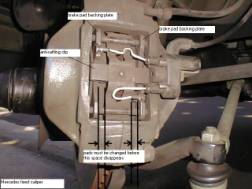
11. Brake pad backing
plate. If this is flimsy it will flex and not allow a good contact between
the rotor and pad forcing you to apply more pressure and therefore more pedal
travel. Fixed by replacing pads with higher quality ones.
*felt most of the
time
12. Brake pad material
itself. If the material is low density it will compress like a sponge. And
if it's a low mu (friction) pad it will require more pressure and therefore
more pedal travel.
*felt all the time
13. Rare, but a
problem on really cheap brake pads: The bonding process used to bond the brake
pad material to the backing plate. A poor process will cause the material
to "squirm" around.
Well those are
the biggies, but not the biggest. The biggest is AIR in the system. Before
you do anything else do a really good and thorough brake bleed. And only use
the fluid it says to use on the cap, DOT 3 or DOT 4 or whatever.
Also, changing
the brake pedal assembly to one with a lower ratio. Remember all lost travel
is multiplied by the pedal ratio, the lower the ratio the less dead travel
at the pedal pad. This also firms up the pedal as you're getting less mechanical
assistance. Just be careful, because if you're brake booster fails it will
take more force on the pedal to come to a stop.
Pedal feel can
also be "tuned" with a different booster.
Cut-in is what
sets the initial point of boost (when it kicks in)
2-stage (knee height)
is what sets how much initial force
Boost ratio is
just as it sounds, it sets how much assist you get
Run-out is the
maximum assist
By lowering the
cut-in and increasing the 2-stage you get a better initial bite sooner. Just
have to be careful you don't go overboard and have the driver eat the steering
wheel at every stoplight (like an '80s Audi).
Brake
Performance
Brake Performance:
Level of brake torque produced and the resistance to brake torque loss, better
known as fade.
Brake Torque=Fluid
Pressure*caliper piston area*pad coefficient of friction*rotor radius
-For piston area
multiply area by 2 for sliding calipers, rotor radius is measured from center
of rotor to the center of the pad
For performance
I do not use the term stopping distance because that involves more than just
the brakes.
I want to make
it clear there is a difference between making a brake system feel better and
actually perform better.
The stopping distance
of a car is not necessarily directly related to the feel. A poor feeling brake
system can have very good performance, i.e. Jaguar. While a great feeling
system can have lousy performance, i.e. Ford Focus
Basically, you
need a bigger rotors and good pads with the best contact patch possible between
the two. Also higher friction levels with higher mu brake pads.
And most importantly.........REALLY
GOOD TIRES!
And you need a
way to get rid of that heat at a faster rate. More rotor mass and/or better
conduction (vented, etc.).
How a car stops
is simple, it takes Kinetic Energy (energy created by motion) and transfers
it to Heat (Thermal) Energy. It does this by the mechanism of friction.
KE=1/2 the mass
of the vehicle multiplied by the square of it's velocity
Brake Power is
determined by the rate of KE to TE transfer, or also know as WORK.
Simply, to stop
sooner you need to transfer Kinetic Energy into Heat Energy faster.
There are no other
tricks; you need higher levels of friction and ways to dissipate the heat
quicker.
The big things
to do to get shorter stopping distance:
1. Best Tires for
the conditions (use common sense here, no Pilots in Feb in Alaska)
2. Higher Friction
Brake Pads and/or rotors
3. Bigger diameter
rotors
4. Calipers with
more piston area
The other things
you can do that give you that extra advantage:
1. LOSE WEIGHT
(the car I mean), less mass, less KE
2. Minimize rotational
inertia of wheels/tires. Get lighter wheels and tires (all else being equal).
Note: the farther away from the center of rotation the mass is the great the
inertia, so a 17" wheel will have greater inertia than a 16" all
else being equal.
3. Try and balance
out the braking, if the rears can do more work it spreads out the work. Less
weight transfer to the front BY MOVING THE BATTERY TO THE TRUNK, stuff like
that.
4. Practice! Get
to know how your system works so you can best utilize it.
5. Don't drive
to fast, remember it the square of the velocity. The amount of KE increase
from 40KPH to 80KPH is not 200%, but 400%
The formula below
is a decent way to estimate what, if any, increase you have in brake torque
after an upgrade:
Brake Torque Increase
%=
[(caliper piston
area new/old) * (effective radius new/old)* (brake pad friction coefficient
new/old)]
-effective radius
is the distance from the center of the hub to the center of the brake pad
-For sliding calipers
multiply the areas by 2
Any answer equal
to 1 means no increase. Any answer less than 1 means you've gone backwards.
Any answer greater than 1 means a torque increase.
This will NOT give
you the actual brake torque, just the difference.
Things like 2-piece
rotors, cross-drilling, slotting, cryogenics, heat-treating are all "at
limit" technologies. In other words they only make a noticeable difference
(if any) at the very limits. If you drive on the street in a manner that actually
utilizes these technologies regularly you're probably dead and not reading
this!
Brakes are as much
art as science, there are just so many different variables involving not only
performance but also feel and consumer wants it becomes a real pain!
Again, you have
to know what you want to get out of your system and where you're going to
use it.
In the end if you
got the cash it won't hurt, but you get to a point of diminishing returns
and you have to wonder!
Brake Fade
Brake fade: the
loss of brake torque due to items other than mechanical failure
Basically, fade
is caused by over use of the brakes to the point where a majority of the fluid
pressure and/or pad friction is lost.�
This is caused
by heat, as heat is created in the brake system it causes the brake fluid
to boil and that introduces air into the system.�
If enough brake fluid is transformed into a gas you will not be able
to create the required brake pressure to stop the vehicle.
On top of this
the same heat causing the fluid to boil is also breaking down the pad and
dropping its coefficient of friction.� This
is commonly referred to as pad fade.
To avoid fade is
very easy, you can use a fluid with a higher boiling point and/or a pad with
a more advantageous temperature vs. coefficient of friction curve.� You can also introduce cooling into the system
with brake air ducts, vented rotors, rotors with more vent surface area and
overall better ventilation in the corner area.
Also, venting built
up gases under the pad was a big problem, but pad tech has come so far that
it's not something I would worry about (assuming your using race pads for
racing). Again it's one of those things that are there but only makes a very,
very, very minor difference (if any) most of the time.
Brake
Feel and it�s Benefits
Brake feel: pedal
effort and pedal travel for any given desired deceleration. Ease of brake
pressure modulation, accuracy and precision of modulation. Feedback through
the pedal "describing" pad rotor contact dynamics and pressure fluctuations.
Benefits of "better"
feel:
Brake feel is just
like steering feel. The better the feel/feedback is the more of the inherent
performance you will actually be able to use.
Imagine a car that
has 1.0g of lateral grip, but has lousy steering. Too light, completely dead,
nothing happens just off-center, poor linear response and too much or too
little ratio.
How much of that
great 1.0g are you ever going to be actually using with poor steering?
Same with brakes.
Improving feel will allow you to better use what you have.
However, it will
not objectively increase brake performance. If you are already getting the
max out of you system then better feel will not get you more.
Things like steel
lines, stiffer calipers affect feel, not performance. Only force applied,
torque arm and friction do that. You can change things like lines, calipers,
pedals and boosters to change the characteristics. Such as, initial bite point
and initial deceleration level, pedal travel and effort, pedal force multiplication.
However, these do not actually produce more brake torque.
What
master cylinder and caliper sizing means to pedal feel
Here is how to calculate mechanical
advantage:
Area of MC * pedal ratio = M
Area of front piston= N
ME= M/N = larger is less effort
(MC-master cylinder)
A larger MC results in...
> less pedal travel
> a higher effort pedal
> less hydraulic advantage
> Works well on vehicles that have high fluid volume requirements
since you can get plenty of flow with reasonable pedal travel.�
Large bore master cylinders tend to give less �feedback� and a somewhat
isolated feel.
A smaller MC results in...
> more pedal travel
> a lower effort pedal
> more hydraulic advantage
> Works well in lighter vehicles
where fluid volume requirements is low and excessive pedal travel is not a
concern.� Small bore master cylinders
tend to give better �feedback� and less isolation from the system.
As you can see there's more advantage
to a smaller bore MC, but some heavy trucks require the fluid only a big bore
MC can provide.
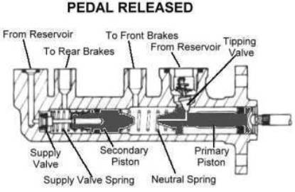
Typical TMC, Tandem Master Cylinder,
most common design used
Caliper:
Larger caliper
piston area results in...
> more pedal
travel
> a softer pedal
> more hydraulic
advantage
Smaller caliper
piston area results in...
> less pedal
travel
> a firmer pedal
> less hydraulic
advantage
Stainless
Steel Braided Brake Lines
SS lines will NOT
improve braking distance.
What will SS lines
do? They will firm up the pedal and will shift the braking pedal feel curve.
The later means that you will reach braking force earlier in the pedal stroke
than without the SS lines.
Anyway, SS lines
do technically firm up the pedal through out the brake pedal stroke. But the
difference may not be noticeable all the time.
SS lines almost
always make a difference at braking events at or over 0.25g, this is equivalent
to the kind of hard braking you see when driving back roads in an aggressive
manner.� Regular rubber brake hoses
will flex initially under high pressure, this is a volume loss that is expressed
as dead travel at the pedal.
With SS lines the
harder you push on the pedal the more the level of the improvement felt.
![]()
Stopping Force:
Equations: (for
ease and consistency try and use meters and kg)
NOTE: Equation 1 does not mean more weight you have more
stopping force, it is just to calculate the stopping force required.� As you can see in Equation 2, the larger the
stopping force is the larger and more aggressive the brakes need to be or
can be.
1.
stopping force
total = weight of car * longitudinal coefficient of friction of tires
2.
Front Force = weight
front + total weight * tire friction * height of CG * (1/wheel base)
3.
Rear Force = weight
rear - total weight * tire friction * height of CG * (1/wheel base)
4.
% front = Front
Force/Stopping Force
5.
% Rear = Rear Force/Stopping
Force
6.
Area of MC * pedal ratio = M
Area of front or rear piston= N
Mechanical Force Ratio= M/N
7.
mechanical force
ratio front = mechanical force ratio * %front
mechanical force
ratio rear = mechanical force ratio * %rear
8.
Stopping Force
= pedal force * brake pad coefficient of friction * mechanical force ratio
* (1/radius of the tire) * brake rotor effective radius
.....solve for
the parameter you need
Lug
Nut Torque
Over-torque of
wheel lug nuts is one of the prime causes of brake rotor distortion. This
can lead to permanent warping of the rotors, uneven wear of the rotors and
pads and lots of brake chatter (NVH).
With today's very
stiff alloy wheels, like from BBS, SSR, Volk, etc., when you torque down the
lug nuts the wheel-mounting surface will force what ever it contacts to take
its shape. Which means whatever that surface looks like will be what the rotor
looks like.
Get a torque wrench
and check the torques on every lug nut and make sure they are within the specs
(which you should be able to find in your owner's manual). And make sure that
every lug nut is torqued down exactly the same. Even if all 5 on a wheel are
within specs, not having all 5 be equal will introduce distortion.
And if you think
that your light alloy wheel can't possibly be that stiff, you wrong they are
MUCH stiffer than the brake rotor or even the hub.
WORD OF CAUTION:
Don't assume that torque the lugs to the lowest range in the spec is the best.
Try and keep it nominal not at the extremes of the range.
Much of the problems
with rotor warp, brake chatter, disk thickness variation can be traced back
to over-torque and uneven torqued lug nuts.
After coming back
from the shop, get that torque wrench and check the lug nuts yourself.
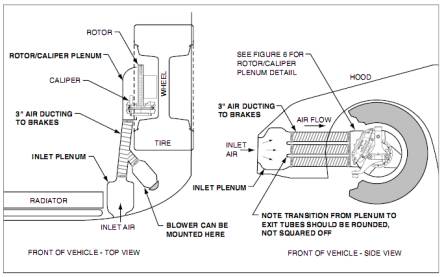
Brake Air Ducts
This is only for
auto-x and racing.
Getting all that
extra air on the brakes going down a straight gets the brakes nice and cool
for the next corner.
Cheap and effective
way to keep rotor temperatures down and therefore reduce fade.
Rear
Brakes
Just want to add
a little warning about the rear brakes. Be VERY careful when it comes to making
changes back there. Upgrading the rears to increase braking power, not just
feel, can be a double-edged knife.
More braking power
to the rears will only do you well if; 1. the balance is woefully off and
the rears are under-utilized, if you can easily lock-up the rears your already
at full potential or 2. you have increased the weight the rear tires carry,
the grip of the rear tires and/or minimized the weight transfer to the front.
Putting more powerful
brakes on the rear alone do nothing more than cause you to lock up or go into
an ABS event sooner. You must increase the rear tires load to benefit from
an increase in the rear brakes power. Otherwise, the rears should be looked
at only from a "feel" standpoint.
Brake
Fluids
Common Brake Fluid
Boiling Points
|| Wet Boiling Point || Dry Boiling Point
Castrol SRF����������������������������� || 518�F���������������� || 590�F
Earl's HyperTemp
421������������� || 421�F���������������� || 585�F
Motul 600�������������������������������� || 420�F���������������� || 593�F
AP-600������������������������������������ || 410�F����������������
|| 572�F
Neosynthetic 610�������������������� || 421�F���������������� || 610�F
ATE-Super Blue����������������������
|| 392�F���������������� || 536�F
Valvoline��������������������������������� || 333�F���������������� || 513�F
Castrol LMA����������������������������� || 311�F���������������� || 446�F
Earl's HyperTemp
300������������� || 300�F���������������� || 568�F
Ford HD��������������������������������� || 290�F����������������
|| 550�F
Wilwood 570��������������������������� || 284�F���������������� || 570�F
PFC-Z rated���������������������������� || 284�F���������������� || 550�F
AP-550������������������������������������ || 284�F����������������
|| 550�F
All brake fluids
absorb moisture, some faster than others (except silicone which is not recommended
for anti-lock brake systems). Castrol SRF resists moisture contamination (non-hygroscopic)
more than any other fluid we tested; therefore change intervals can be greatly
extended. This reduces the effective cost over a season of racing. Many drivers
say that they can run the same fluid all year long with only bleeding off
the fluid in the calipers for each event. This way a can or two will last
all year. Other fluids (hygroscopic type) require additional flushing of the
system for each track event to maintain the lowest percentage of moisture
and the highest boiling point.
FYI - The Castrol
SRF is around $77/container versus $10-15/container for the rest.
Silicone Brake
Fluids
Fluids containing
Silicone are generally used in military type vehicles and because Silicone
based fluids will not damage painted surfaces they are also somewhat common
in show cars.
Silicone-based
fluids are regarded as DOT 5 fluids. They are highly compressible and can
give the driver a feeling of a spongy pedal. The higher the brake system temperature
the more the compressibility of the fluid and this increases the feeling of
a spongy pedal.
Silicone based
fluids are non-hygroscopic meaning that they will not absorb or mix with water.
When water is present in the brake system it will create a water/fluid/water/fluid
situation. Because water boils at approximately 212� F, the ability of the
brake system to operate correctly decreases, and the steam created from boiling
water adds air to the system. It is important to remember that water may be
present in any brake system. Therefore silicone brake fluid lacks the ability
to deal with moisture and will dramatically decrease a brake systems performance.
Brake Fluid and Cold Temps.
Kinematic
viscosities: All brake fluids (DOT 3, DOT 4 and DOT 5) must meet a minimum
viscosity test of not less than 1.5 centistokes at 100� C (212� F) and must
not be more than the following to meet their various classifications (the
larger numbers indicate higher kinematic viscosities just like with motor
oils).
DOT 3 1500 Centistokes at minus 40� C
DOT 4 1800 Centistokes at minus 40� C
DOT 5 900 Centistokes at minus 40� C
Higher kinematic viscosities means it "flows easier" at the cold
temps.
A centistokes is 1 mm^2/s
MINIMAL boiling points
for these specifications are as follows:
|| Dry Boiling Point ����� ||
Wet Boiling Point
DOT 3 ������������� || 401�F ��������������������� || 284�F
DOT 4 ������������� || 446�F ��������������������� || 311�F
DOT 5 ������������� || 500�F ��������������������� || 356�F
DOT 5.1 ���������� || 518�F ��������������������� || 375�F
Poly Glycol Ether
Based Brake Fluids
Fluids containing
Poly glycol ethers are regarded as DOT 3, 4, and DOT 5.1. These type fluids
are hygroscopic meaning they have an ability to mix with water and still perform
adequately. However, water will drastically reduce the boiling point of fluid.
In a passenger car this is not an issue. In a racecar it is a major issue
because as the boiling point decreases the performance ability of the fluid
also decreases.
Poly glycol type
fluids are 2 times less compressible than silicone type fluids, even when
heated. Less compressibility of brake fluid will increase pedal feel. Changing
fluid on a regular basis will greatly increase the performance of the brake
system.
FLUID SPECIFICATIONS
All brake fluids must meet federal standard #116. Under this standard are
three Department of Transportation (DOT) minimal specifications for brake
fluid. They are DOT 3, DOT 4, and DOT 5.1 (for fluids based with Polyalkylene
Glycol Ether) and DOT 5 (for Silicone based fluids).
Wet vs. Dry Boiling
Point
WET BOILING POINT
- The minimum temperatures that brake fluids will begin to boil when the brake
system contains 3% water by volume of the system.
DRY BOILING POINT
- The temperatures that brake fluid will boil with no water present in the
system.
How does water
get in there?
Water/moisture
can be found in nearly all brake systems. Moisture enters the brake system
in several ways. One of the more common ways is from using old or pre-opened
fluid. Keep in mind, that brake fluid draws in moisture from the surrounding
air. Tightly sealing brake fluid bottles and not storing them for long periods
of time will help keep moisture out. When changing or bleeding brake fluid
always replace master cylinder caps as soon as possible to prevent moisture
from entering into the master cylinder. Condensation, (small moisture droplets)
can form in lines and calipers. As caliper and line temperatures heat up and
then cool repeatedly, condensation occurs, leaving behind an increase in moisture/water.
Over time the moisture becomes trapped in the internal sections of calipers,
lines, master cylinders, etc. When this water reaches 212� F the water turns
to steam. Many times air in the brake system is a result of water that has
turned to steam. The build up of steam will create air pressure in the system,
sometimes to the point that enough pressure is created to push caliper pistons
into the brake pad. This will create brake drag as the rotor and pads make
contact and can also create more heat in the system. Diffusion is another
way in that water/moisture may enter the system.
Diffusion occurs
when over time moisture enters through rubber brake hoses. The use of hoses
made from EPDM materials (Ethlene-Propylene-Diene-Materials) will reduce the
amount of diffusion OR use steel braided brake hose with a non-rubber sleeve
(usually Teflon) to greatly reduce the diffusion process.
DOT what?
DOT: Acronym for
"Department of Transportation" -- an American federal agency or
"Department of Transport" -- a British agency
DOT 3: This brake
fluid has a glycol base. It is clear or light amber in color. Its dry boiling
point is 401� minimum and wet boiling point of 284� minimum. It will absorb
1 to 2 percent of water per year depending on climate and operating conditions.
It is used in most domestic cars and light trucks in normal driving. It does
not require cleaning the system and it can be mixed with DOT 4 and DOT 5.1
without damage to the system. The problem with it is that it absorbs moisture
out of the air and thereby reduces its boiling point. It can also damage the
paint on a vehicle.
DOT 4: This brake
fluid has a borate ester base. It is clear or light amber in color. Its dry
boiling point is 446� minimum and wet boiling point of 311� minimum. It is
used in many European cars; also for vehicles in high-altitude, towing, or
high-speed braking situations, or ABS systems. It does not require cleaning
the system and it can be mixed with DOT 3 without damage to the system. The
problem with it is that it absorbs moisture out of the air and thereby reduces
its boiling point. It can also damage the paint on a vehicle.
DOT 5: This brake
fluid generally has a silicone base. It is violet in color. Its dry boiling
point is 500� minimum and has no wet boiling point in federal DOT 5 specifications.
It is used in heavy brake applications, and good for weekend, antique, or
collector cars that sit for long periods and are never driven far. It does
not mix with DOT 3, DOT 4, or DOT 5.1. It will not absorb water and will not
damage the paint on a vehicle. It is also compatible with most rubber formulations.
The problem with it is that it may easily get air bubbles into the system
that are nearly impossible to remove, giving poor pedal feel. It is unsuitable
for racing due to compressibility under high temperatures. If as little as
one drop of water enters the fluid, severe localized corrosion, freezing,
or gassing may occur. This can happen because water is heavier and not mixable
with silicone fluids. It is unsuitable for ABS.
DOT 5.1: This brake
fluid has a borate ester base. It is clear or light amber in color. Its dry
boiling point is 500� minimum and wet boiling point of 356� minimum. It is
used in severe-duty vehicles such as fleets and delivery trucks, towing vehicles,
and racecars. It can be mixed with DOT 3 or DOT 4 without damage to the system.
It maintains higher boiling point than DOT 3 or DOT 4 fluids due to its higher
borate ester content. It is excellent for severe duty applications. The problem
with it is that it costs more than other fluids and there is limited availability.
It also absorbs moisture out of the air and thereby reduces its boiling point.
It can also damage the paint on a vehicle.
What causes a mushy
pedal?
DOT 5 fluid is
not hygroscopic, so as moisture enters the system, it is not absorbed by the
fluid, and results in beads of moisture moving through the brake line, collecting
in the calipers. It is not uncommon to have caliper temperatures exceed 200�
F, and at 212� F, this collected moisture will boil causing vapor lock and
system failure. Additionally, DOT 5 fluid is highly compressible due to aeration
and foaming under normal braking conditions, providing a spongy brake feel.
Brake
Bleeding/Flushing
One thing that
is ALWAYS true never let the TMC (master cylinder) on an ABS, traction control
(TCS) or electronic stability program (ESP) car run dry. You'll never get
the air bubbles out again by hand. To be honest there is more than one right
way and if you found something that works, why fix what's not broken.
Just FYI-
At the factory
this is how it's done. They do it all one shot.
First you mount
the Evac-Fill head unit to the reservoir then all air is evacuated from the
system, creating a vacuum. Then fluid is forced through the system at high
pressure.
Then the car is
delivered and people complain about mushy pedal!
Just some more
stuff:
I e-mailed a Tech
at Ford I used to work with on the proper bleed sequence. Since techs do these
all the time and engineers don't I'll take his advice.
This is it:
Doing nearest or
most distant doesn't matter. What matters is if the brake system is a diagonal
or front-rear system.
Quick definition:
diagonal means that one circuit in the master cylinder feeds the front driver's
side and the rear passenger side. The other circuit the front passenger's
and rear driver's. Both circuits are of equal volume. Front-Rear means that
one circuit supplies the front calipers, while the other the rear calipers.
The Primary circuit (front caliper circuit) is of greater volume.
All you need to
do is make sure you do the circuits together. For instance, on most passenger
cars it's a diagonal system. So you want to do the driver's front and passenger's
rear together, which you do first is not all that important. But he does agree
that the tradition is to do the rear first. Or best to get a friend and do
both at the same time. And take your time (he told me to make sure I added
this).
Same holds true
for the Front-Rear systems. Do fronts together and rears together. Usually
only trucks, SUVs and very heavy front bias cars (Ford Crown Vic) have a Front-Rear
system.
Just FYI- Diagonal
is used so that if one circuit fails the vehicle is still stoppable in a stable
manner as at least one front and rear wheel is braking and on opposite sides.
Front-Rears are used on heavy, front-bias cars require a lot of volume up
front.
ABS Bleeding:
Do 3 normal bleeds
and then do
An ABS stop if
you still feel that air might be trapped. Then do 1 more
Bleed. The ABS
stop would have flushed the air out.
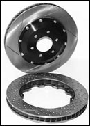
2-Piece rotors
I have seen a lot
on 2-piece rotors. Some of the information contained in them is correct some
is mythical.
Some definitions.
2-Piece rotor:
A brake disc rotor that has a separate hat (cap) usually made from a lightweight
metal. There are two types of common 2-piece street rotors. One uses a bolted
hat and the other a pinned hat (also known as a "floating rotor"
design).
The bolted type
is just what it sounds like. Usually an aluminum hat bolted to a cast iron
rotor. The only real benefit of this design is weight savings. However, weight
savings tend to be only 10-20%, all else being equal, but with a 50-75% price
increase.
The pinned type
has usually stainless steel pins that attach the aluminum hat to the rotors.
This allows the rotor to "float" on the pins. The great advantage
of this design is that it allows the rotor to move freely. When the rotor
expands and contracts there is much less chance of binding or distortion.
As you can imagine this cuts down on warping and uneven wear (DTV). The disadvantage
of this design is really high costs and increased NVH.
As far as better
heat conduction, not really. It does help a bit, buts it's not enough to make
it worth the extra cost. The nice think about the weight savings is you can
get a larger rotor with out taking a weight penalty.
- It may help keep
your wheel bearings cooler.
My opinion:
2 piece floating
(pinned) rotor is worth every penny. This is good technology, yeah they cost
a ton but they do the job.� They keep
the rotor even through out operating temperature range and they keep down
DTV problems better than anything I've ever seen.�
Be sure they're the pinned hat type and not the bolted hat type.
Warped Rotors
Note: DTV stands
for disk thickness variation, caused by uneven rotor wear and/or pad material
deposited on the rotor. Pad deposit usually happens when brakes are hot and
you let them "sit cool"; you should drive around at slow speeds
while your brakes cool.
Warped Rotor:
Cut an imaginary
plane through the center of the disc part of the rotor that is parallel to
both surfaces of the disc, this is done when rotor is new.
If the rotor is
warped this imaginary plane (now part of the disc) will no longer be parallel
to a reference plane, that reference plane was also parallel to both surfaces
of the disc when the disc was new.
In essence a warped
rotor is a rotor that is deformed throughout its thickness.
A rotor with DTV
(surface imperfection) issues:
The imaginary plane
above is still parallel to the reference plane mentioned in the warped rotor
definition, however the two surfaces of the disc are no longer parallel to
each other.
Think of 2 identical
planks of wood.
1st plank you take
a planer to it in a haphazard way to the surface making the surface wavy.
This is a surface condition.
You can sand the
surface down to get back to a smooth surface.
2nd plank you steam
heat and then bend around a steel pipe. This plank is warped. You can sand
all you want, but you'll never get it straight again.
You can see why
it's so easy to mistake one for the other; on the surface it all looks "warped"
Of course if the
rotor is too thin then it can't be "sanded" smooth, but a warped
rotor can't be turned no matter how thick it is.
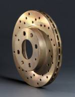
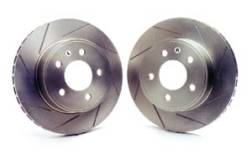
Cross
Drilled and Slotted Rotors
Cross-drilled rotors:
Disks
that have been drilled through with a non-intersecting pattern of radial holes.
The objects are to provide a number of paths to get rid of the boundary layer
of out gassed volatiles and incandescent particles of friction material and
to increase "bite" through the provision of many leading edges.
The advent of carbon metallic friction materials with their increased temperatures
and thermal shock characteristics ended the day of the drilled disc in professional
racing. They are still seen (mainly as cosmetic items) on motorbikes and some
road going sports cars. Typically in original equipment road car applications
these holes are cast then finished machined to provide the best possible conditions
by which to resist cracking in use. But they will crack eventually under the
circumstances described in another section (see Cracking). Properly designed,
drilled discs tend to operate cooler than non-drilled ventilated discs of
the same design due the higher flow rates through the vents from the supplemental
inlets and increased surface area in the hole. That's right, inlets, the flow
is into the hole and out through the vent to the OD of the disc. If discs
are to be drilled, the external edges of the holes must be chamfered (or,
better yet, radiused) and should also be peened.
Slotted:
Shallow, sharp edged but radiused bottom grooves milled into cast iron discs to provide leading edges for bite and a path for the fire band of gases and incandescent friction material to be dissipated through. If the slots fill up with pad material, the system is operating at too high a temperature.
For the track they
work.� Not as dramatically as the ads
will lead you to believe, but they do a good job of keeping the pad surface
"clean" when they get really hot and they do a good job of venting
gases.� Again though, with modern pads
neither of the issues mentioned are that severe now a days.
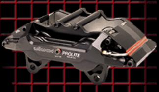
Brake Calipers
The caliper�s basic
function is to force the pads against the rotor.� A caliper is made of 3 basic groups, the housing
(body), the pistons and the mounting bracket.� The pistons sit in the housing and are the components that directly
push the pads against the rotor.� The
housing is there basically to hold and flow fluid to the pistons and give
the piston somewhere to live.
There are 2 families
of calipers, the sliding caliper and the fixed caliper:
The sliding caliper
is by far the most common and is mostly likely what�s on your car.� It has pistons only on the inboard side and
the caliper slides on guide pins to force the outside pad against the rotor.
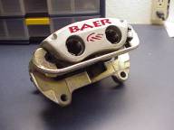
The fixed caliper
has a single (monobloc) or 2 piece bolted housing and piston(s) on both the
outboard and inboard side.� The caliper
is completely stationary and each side applies pressure to the pads independently.
What�s the difference?�
The major differences between the fixed and sliding calipers is weight
and stiffness.� A fixed caliper in general weighs less and
has significantly less flex.� This
means better pedal feel.� Fixed calipers
also tend to have a lower profile allowing a larger rotor in the same wheel.� Advantage of a sliding caliper is cost, they
are usually much less expensive.
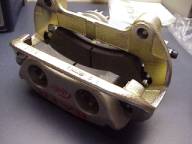
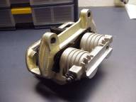
Single piston and
multi-piston Calipers:
Most sliding calipers
are of the single piston type, which means one large piston does all the work.�
Dual-piston calipers are becoming more popular.��
Most fixed calipers are 4 piston type, 2 pistons on each side.� There are 2 piston fixed and some go as high as 8 pistons total.����
The advantages
of multiple pistons is:�
1. More piston
area more force on pad and you can fit more piston in any given rectangle
with smaller diameter pistons (like engine valves in the heads).
2. A lower profile
caliper as 2 small pistons have a �lower height� than one big piston.�
This means less flex since the distance from the point of application
to the bridge (top strap) of the caliper is less.
More pistons usually adds more cost
and low force braking feel is softer.
Dynamic Brake Control
Is a "Panic
Assist Feature" what it does is measure the velocity of pedal travel
by using either a sensor on the pedal or in the booster. If a certain threshold
is met then the booster (if it's an electronic booster) or the DSC pump will
apply max pressure. It doesn't actually stop the car in any shorter distance
than you could.
The reason for
DBC is that it's been established than many people when emergency braking
will ease off the brake pedal a little after the initial stab. DBC keeps the
pressure up even if you let off. This can be a real pain when your trying
to modulate the brakes yourself as most systems have a pretty low threshold
and just aggressive braking is seen as a "panic stop."
This feature also
requires a functioning ABS, the expensive systems are electronic so if the
ABS fails the feature is disabled, but some cheaper cars have a purely mechanical
system and a failed ABS is not detected. You can imagine what happens when
you have max brake power and no ABS.
Anti-Lock Brakes
Please go to this website: http://www.geocities.com/nosro/abs_faq/
|
Glossary of
Braking Terminology By Stephen
Ruiz, Engineering Manager ABS: Acronym for Anti-Lock Braking
system. Anti Lock braking systems sense the speed and rate of deceleration
of each of the wheels of a vehicle independently and, through a microprocessor
control system, act to prevent lock up of any of the tires under braking
force by cycling the line pressure to the wheel that is approaching
lock up. Most current passenger cars are fitted with ABS.
Braking efficiency: The ratio of actual deceleration
achieved on a given surface compared with the theoretical maximum.
Caliper: The "hydraulic clamp"
portion of a disc brake system. Manufactured from either ferrous or
non-ferrous material and bolted firmly to the suspension upright (or
"knuckle") the caliper holds the pads in place and, through
the action of hydraulic pistons actuated by the master cylinder, forces
them against the rotating surface of the disc when pressure is applied
to the brake pedal. 1. Fixed caliper: A brake caliper
in which two or more pistons are arranged on either side of a rigid
body with the disc in the center. Due to its inherent stiffness the
fixed caliper is the only design suitable for racing categories where
it is allowed and is the preferred design for high performance cars.
2. Floating caliper: A design in
which a single or dual piston is located inboard of the disc and the
outer body of the caliper slides on suitable surfaces in reaction
to piston pressure. The piston forces the inboard pad against the
disc while the sliding outer body clamps the outboard pad against
the disc. The inherent lack of rigidity in the design, compared to
fixed caliper design, combined with the friction inherent in the sliding
outer body makes this design less suitable for racing and high performance
use. The design is well suited for use with front wheel drive as the
absence of any outboard pistons allows greater negative (inward) wheel
offset. In all applications, this caliper type is simpler to manufacture
and affords more packaging flexibility for zero or even negative scrub
radius front suspension designs. It is sometimes used in the rear
on an application that has a fixed design in the front. 3. Open caliper: The design of
fixed caliper in which the "window" through which the pads
are inserted is structurally open. This design, while less expensive
to manufacture, significantly reduces caliper rigidity. 4. Closed caliper: The design of
fixed caliper in which the "window" through which the pads
are inserted is structurally reinforced by a bridge. 5. Caliper bridge: The structural
reinforcement across the open face of a fixed caliper. In order to
be effective the bridge must be rigidly bolted in place with high
tensile fasteners. Sliding - see Floating Caliper
Carbon metallic: This is a trademark of the Performance
Friction Corporation. Pad friction compounds containing large percentages
of pure carbon along with various metallic elements. Pioneered by
Performance Friction Corporation these compounds offer very constant
coefficients of friction vs. temperature characteristics along with
increased thermal capacity. The disadvantage is that, since they both
operate at higher temperatures and their temperature rises to operating
temperature faster than other compounds, they increase thermal shock
to the disc and increase thermal conduction to the caliper pistons
and brake fluid. As a result, it is recommended to not use drilled
discs with carbon metallic pads. Cast iron: Metallic iron containing more
than 2% dissolved carbon within its matrix (as opposed to steel which
contains less than 2%)and less than 4.5%. Because of its cost, relative
ease of manufacture and thermal stability cast iron (sometimes referred
to as "gray cast iron" because of its characteristic color,
but is actually a more specialized material for brake applications)
is the material of choice for almost all automotive brake discs. To
work correctly, the parts must be produced at the foundry with tightly
monitored chemistry and cooling cycles to control the shape, distribution
and form of the precipitation of the excess carbon. This is done to
minimize distortion in machining, provide good wear characteristics,
dampen vibration and resist cracking in subsequent use.
Disc: The rotating portion of a disk
brake system. Mechanically attached to the axle, and therefore rotating
with the wheel and tire the disc provides the moving friction surface
of the system while the pads provide the stationary friction surfaces.
Except for racing, discs are normally manufactured from one of several
grades of cast iron. Some European front drive passenger cars, where
the rear brakes do very little work, are using aluminum metal matrix
rear discs to save weight. Most professional racing cars use carbon/carbon
discs.
3. Solid disc: A disk cast as a
solid piece suitable for light cars not subjected to extreme braking.
Dust boots: Rubber shields that fit over the
exposed portion of the caliper pistons to prevent the ingress of dust
and road crime. As no known rubber compound will withstand the temperatures
generated by racing brakes, dust boots are not used in racing and
should be removed before truly hard driving for extended periods.
Effective temperature range: The range of operating temperatures
within which a pad material remains effective. As with coefficient
of friction, this should be used for comparative purposes only as
measurement procedures very between manufacturers and pad temperatures
are strongly affected by disc mass and rate of cooling.
Fireband: The name given to the boundary
layer of out gassed volatiles and incandescent particles of friction
material that rotates with the disc.
Modulation: The term given by the process
by which the skilled driver controls the braking torque to maintain
maximum retardation without locking wheels. Because the human being
modulates most efficiently by force rather than displacement, effective
brake modulation requires minimum pedal travel and maximum pedal firmness.
OE: This is an abbreviation for Original
Equipment. Please see the section "Original Equipment".
Sometimes it is used as an abbreviation to refer to the Original Equipment
Manufacturer (but more correctly referred to as the OEM).
Off brake drag: A condition in which the caliper
pistons do not fully retract when line pressure is released. Off brake
drag increases temperature and wear while decreasing acceleration,
top speed and fuel mileage. It is caused by either non-optimum seal
design, seals that have been hardened by thermal stress or excessive
disc run out.
Plot shape: The shape of the friction plot
during a long brake application it is easier and more efficient for
the driver to add pedal pressure than to remove it. Therefore the
easiest pad to modulate exhibits a high initial bite followed by a
gradual decrease in coefficient throughout the stop. If the level
of friction rises throughout the stop, brake modulation will be very
difficult.
Reservoir: The container in which brake fluid
is stored to provide a source of fluid for the master cylinder(s).
The reservoir must have sufficient volume to allow fluid displacement
equivalent to wearing the pads down past the backing plates. It must
also be sealed to prevent the absorption of moisture by the highly
hygroscopic brake fluid. Typically the reservoir cap is fitted with
an electrometric bellows open to atmosphere but sealed from the fluid.
1. Disc: Shallow, sharp edged but
radiused bottom grooves milled into cast iron discs to provide leading
edges for bite and a path for the fire band of gases and incandescent
friction material to be dissipated through. If the slots fill up with
pad material, the system is operating at too high a temperature. 2. Pad: Radial grooves molded or
cut into the surface of the pad to provide a path for fire band dissipation
and to double the number of leading edges and improve bite. Some long
pads also have a longitudinal groove.
Thermal shock: Disc materials, particularly cast
iron are degraded not only by the magnitude of temperatures reached,
but also by the "delta" temperatures the speed at which
the temperature increases and decreases. Cracks are largely caused
by weakening of the bonds between the grains of the metal brought
about by rapid change in temperature.
|
"Mini brake
test"...(I no longer own the 328i)
2 friends and me
performed a little brake test this morning.
I have a friend
that works at a small airport and was able to gain access to a nice flat and
large area. Not a runway.
We brought my 2000
BMW 328i with sport package and new WRX.
Atmosphere Conditions
at the time (benefit of being at an airport):
Temp: 54 F, Humidity
55%, Barometer 30.28in and rising, Wind 6 MPH East, partly cloudy
Surface was perfectly
dry and smooth. Surface was concrete.
The vehicles:
2002 Impreza WRX
Sportwagon with manual transmission, SSR Competition wheels, 225/45ZR17 Bridgestone
Potenza S-03 PP tires, Tein H-Tech springs, rear 20mm anti-roll bar. All else
stock, including brakes.
2000 BMW 328i with
manual transmission and the sport package, all stock. The tires: 225/45ZR17
Michelin Pilot Sports.
The WRX tires have
650 miles on them; the BMW tires have 7000 miles on them. All pressures where
set at the recommended settings as posted on the driver's doorjamb.
WRX has 720 miles
on the pads; the BMW has 7000 miles on the pads.
Some important
numbers on the BMW:
Curb Weight: 3197lbs,
Weight distribution front/rear: 50.5/49.5, brake setup: single piston sliding
calipers front and rear with 11.8 inch front rotor and 11.6 rear rotor both
ventilated.
Some important
numbers on the WRX Sportwagon:
Curb Weight: 3165lbs,
Weight distribution front/rear: 58.5/41.5,
brake setup: dual
piston sliding caliper up front and single piston sliding caliper in the rear
with 11.4 ventilated rotor in front and 10.3 inch solid rear rotor.
Test procedure:
10 consecutive
stops from 60MPH (using the car's speedometer, so chances are it wasn't exactly
60MPH). That's all I had the time to do.
Consecutive means
the time it took to turn around get back to the start and then 30 second wait.
3 drivers. Myself,
worked as a brake engineer and have experience. Driver 2 is a "car guy"
and knows how to drive. Driver 3 is good driver but not a "car guy."
All numbers are
rounded to nearest whole number, so no 120.5 feet, that would be listed as
121 feet. I do this because of the nature of the test and the measuring equipment.
Which consists of 10 cones spaced 15 feet apart and a tape measure.
The BMW's DSC (ESP
system) was turned off, so both cars had ABS only working.
For time reasons
I was the only driver to do all 10 runs.
The results (all
in feet):
------------------------WRX----------------------BMW
Run 1.......................121............................117
Run 2.......................121............................116
Run 3.......................121............................116
Run 4.......................123............................117
Run 5.......................125............................117
Run 6.......................125............................119
Run 7.......................128............................121
Run 8.......................133............................121
Run 9.......................133............................121
Run 10......................133............................121
Take these numbers for what their worth. Please keep
in mind the difference in tires and miles on them. And the "test equipment"
used. Disclaimer: This is for entertainment purposes only.
Appendix
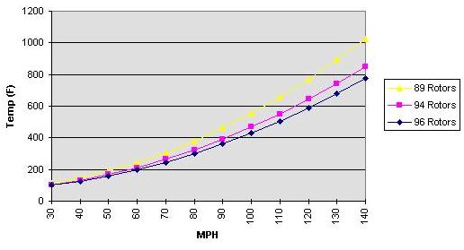
Typical Temperature Curve for a Rotor
Typical Front
Brake Setup
Typical Rear Brake Setup