Cellport 3000 VR into a ’98 BMW 528i
By Mark Sandler (mark@sandler.org)
I installed the Cellport 3000 VR universal hands free system (for my Nextel i1000plus) in my E39, a 1998 BMW 528i. I wanted to take advantage of as much of the phone prewiring as I could. The car has prewiring for dedicated speakers, radio mute, a microphone and an antenna.
I did a lot of testing before cutting any of the Cellport wiring. I didn’t cut any BMW wires, just made harnesses or connectors for testing. Please be advised that this installation will void the warranty on the Cellport unit and is definitely not BMW approved. Try this at your own risk and expense. Other disclaimer-type language applies.
I used DRaven’s article, “Put a Nokia car kit in a '98 5er”, as the basis for my installation.
The only prewiring I could not successfully take advantage of was the microphone wiring. I did not buy the BMW microphone (#84 31 8 380 338 - approx. $50). Instead, I tried connecting the Cellport mic to the prewiring (by making the necessary connections on the DB-25 adapter and at the 18 pin harness). I heard a noise through the phone system while a call was in progress. In the end, I ran the Cellport mic cable from the overhead console (where the BMW mic is located) to the center console and thus ignored the prewiring for the microphone. Running the wire was pretty easy.
I found a few differences with the article I mentioned above in the 18 pin harness in my center console: pins 5, 10 & 12 were unused. My 18 pin female harness seemed to look like the following (I did not map the colors). The DB-25 in the trunk seems to about the same as mentioned in the previously mentioned article.
Pinout of the 18 pin harness located in the center console
1 - Pin 11 of DB-25 in trunk
2 - Pin 12 of DB-25 in trunk
3 - Pin 18 of DB-25 in trunk
4 - Pin 1 of DB-25 in trunk
5 - Not used (no wire)
6 - Pin 6 of DB-25 in trunk
7 - Pin 23 of DB-25 in trunk
8 - Ignition 12V (Nice and quiet, no engine noise, etc.)
9 – Unknown (this is labeled “IBus” on a CPT7000 wiring diagram)
10 - Not used (no wire)
11 – Unknown (this is labeled “Tel On” on a CPT7000 wiring diagram)
12 - Not used (no wire)
13 - Pin 8 of DB-25 in trunk
14 - Pin 21 of DB-25 in trunk
15 – Unknown (this is labeled “58G” on a CPT7000 wiring diagram)
16 - Pin 7 of DB-25 in trunk
17 – Ground (nice and quiet, no engine noise, etc.)
18 - Pin 24 of DB-25 in trunk
Comments about the prewiring
- I think the microphone prewiring is for a balanced mic hence the positive, negative and shield connector. This may be why I had trouble with the mic.
- The ground wire in the harness is quiet. I tried grounding to the chassis but it wasn’t any better, so I stuck with harness for the convenience of installation. You may need to ground to the chassis if you are getting noise in the system.
- The speaker wiring connects to speakers on the left and right but with a mono signal.
Extra Parts Needed
- 3/32” mono phono jack (Radio Shack 274-292)
- 3/32” right angle mono phono plug (Radio Shack 274-243)
- Header connector (like Radio Shack 910-1530), not avail in the Radio Shack store
- Dual conductor shielded speaker cable (Radio Shack 278-514)
- FME - mini UHF adapter (female to female), not avail at Radio Shack
- DB-25 male connector (Radio Shack 276-1429)
- DB-25 hood (Radio Shack 276-1549)
- Panavise 4” pedestal (Slimline - Model 726-04sf)
Preparation Instructions
1. Build the speaker cable. Solder the two conductors of a 12 inch piece of the speaker cable to the 3/32” phono plug (positive is the tip, negative is ring, the shielding should not be connect at either end).
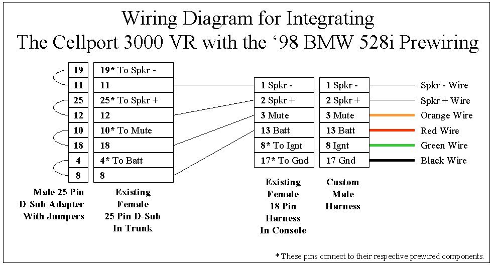
2. Build the custom harness (see wiring diagram). It should be about 12 inches long. This will require soldering the fours ends of the Cellport wire and the two conductors of the speaker cable (made in step 1) to the appropriate pins of the Header connector. I keep the Cellport wiring harness fuses in the system, but cut away most of the Cellport wire. See Picture 1.
3. Build the DB-25 adapter (see wiring diagram)
4. Modify the Cellport amplified speaker box (see detailed instructions below)
Installation Instructions
Most of my wiring is located under the console box.
- Remove armrest from center console.
- Remove center console box.
- Install amp box in area under the armrest. See Picture 2.
- Run wires down into lower console area (under the box). See Picture 3.
- Run microphone from desired location back to center console box area (leave slack on both ends) See Picture 4.
- Connect speaker phono plug (from the custom harness) to amp box phono jack.
- Connect custom harness to prewiring.
- Connect Cellport connectors (according to their instructions).
- Connect antenna lead from the Cellport to the antenna wire using the FME to Mini UHF adapter. Also connect the two antenna connectors in trunk.
- Attach DB-25 adapter to female DB-25 connector in truck. See Picture 5.
- Check all connections.
- Test Cellport and phone.
- Reinstall armrest.
- Reinstall center console box.
- As for the Cellport cradle, I installed it on a short pedestal mounted to the console deck. See Picture 6.
- That’s it. Enjoy!
So what do you get once you are finished? When you place a call, the radio will display “Phone” and the sound system will mute while the phone is in use. The volume of the speakers is controlled by the phone volume (not the steering wheel). It sounds much better than using the amplified speaker provided. Also, the Cellport will charge the phone while the ignition is on otherwise the phone will turn off after 45 seconds.
Details for modifying the Cellport Amplified Speaker Box
The basic idea is to remove the built-in speaker and just connect the leads to a 3/32” phono jack mounted to the box. I used the amp to drive the onboard car phone speakers. The conversion details follow:
- Remove the mounting bracket and thumbscrews. (not needed)
- Open the speaker box.
- Unplug the speaker wire plug from the circuit board.
- Unsolder the leads to the speaker. Note which lead is positive and negative. (The speaker is no longer needed).
- Solder the two speaker wires to the 3/32” phono jack (Positive lead to center pin connector, Negative to the outside connector)
- Drill a hole in the center of the side of the speaker box. (on the long side that the circuit board speaker plug is close to).
- Reconnect the plug to the circuit board.
- Twist the jack and wires a few times.
- Mount the jack in the hole so the jack faces out.
- Replace the cover on the box.
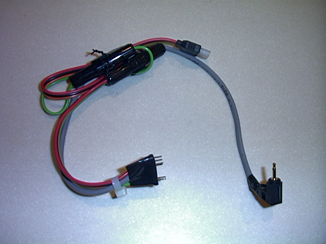
Picture 1. This is the Cellport wiring with the custom connectors. The mono phono plug is connected to the modified Cellport amp.
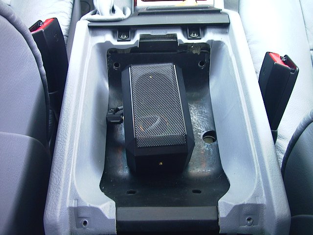
Picture 2. The Cellport amp located under the armrest. The mono phono plug from the harness is connected on the left.
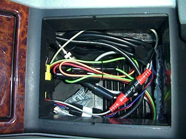
Picture 3. Center console box with wires.
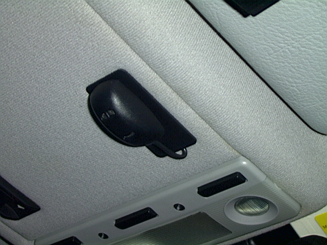
Picture 4. Cellport microphone is installed in the BMW microphone location.
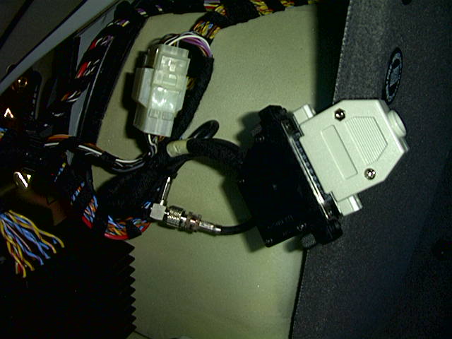
Picture 5. This is the Male adapter connected to the DB-25 female connector in the truck. Also notice the two antenna connectors are connected.
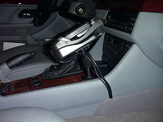
Picture 6. The Cellport cradle is mounted to the Panavise pedestal and attached to the console with heavy-duty double-sided tape. The wires disappear into a hole behind the molding and run along the inside of the center console to the console box.